 2025-08-13
By
 Canglong Group
735
Steel Building Structural Design: Load Paths, Structural Systems and Design Checks
Steel building structure design is the work of sizing every member, connection and foundation so that the loads on your site reach the ground safely. Most of it is unglamorous arithmetic, and it is the one part of a steel building project that cannot be fixed later with paint, thicker cladding or a bigger budget.
This guide is written for owners, developers and contractors who need to know what a designer actually does with their project before a single member is cut. It covers the inputs that decide every section size, how wind, snow and seismic actions change the frame, the six structural systems in normal use, what changes once cranes or heavy racking are involved, the serviceability checks that usually govern, what happens at the connection and foundation interfaces, and how the work moves from calculation to approved fabrication drawings.
It is not a product catalogue, and it is not a substitute for a licensed engineer of record. Where a number depends on a code, we say which one, because the answer changes between EN 1993 (Eurocode 3), AISC 360, IS 800 and AS 4100.
Five numbers decide most of a frame before any software is opened:
- Span and eave height
- Bay (frame) spacing
- Wind speed, snow load and seismic zone at the actual site coordinates
- Crane capacity and duty class, or racking height and forklift type
- Soil allowable bearing capacity
Change any one of those and the steel tonnage moves. Change two and you may need a different structural system altogether.
What Steel Building Structure Design Actually Produces
A completed design package contains three things, and clients are often surprised that the third one is not included by default.
| Deliverable | Contents | Who uses it |
|---|---|---|
| Structural calculation report | Load cases and combinations, member utilisation ratios, deflection and drift results, connection checks, foundation reactions | Approving authority, client’s engineer, insurer |
| Drawing set | General arrangement (GA), shop/fabrication drawings, erection sequence drawings, bolt lists, bill of materials | Fabricator and erection crew |
| Foundation interface data | Column reactions (vertical, horizontal, uplift) and anchor bolt setting-out layout | Local structural engineer who sizes the footings |
That split trips up a lot of export projects. A steel supplier designs and fabricates the superstructure and issues the reactions; the foundations are designed by an engineer registered in the country of construction, because soil behaviour, frost depth and building-permit responsibility are all local matters. If a supplier offers you “foundation included” without a geotechnical report in hand, be careful.
Design Inputs: Eight Things That Decide Every Section
These are the questions a design team should ask before modelling starts. Missing items do not stop the job. They just come back as a redesign in week three.
| Input | What it changes | Where the value comes from |
|---|---|---|
| Site coordinates and exposure | Wind speed, terrain category, snow zone, seismic zone, altitude, topography factor | National wind/snow maps, ASCE 7 / EN 1991-1-4 / IS 875; site coordinates, not just a city name |
| Geometry | Span, length, eave height, roof pitch, bay spacing, mezzanine levels | Client process layout |
| Occupancy and equipment | Imposed floor load, machine point loads, vibration checks, racking tolerances | Occupancy table in the applicable code + machine data sheets |
| Crane data | Column section, crane girder, longitudinal bracing, foundation size — often the single biggest driver on the job | Capacity, span, hook height, duty class, wheel loads, number of cranes |
| Environmental actions | Wind, snow, seismic, temperature range | Code maps plus local authority requirements |
| Geotechnical conditions | Foundation type, depth, pile vs pad, uplift resistance | Site investigation report: bearing capacity, groundwater, frost depth, seismic site class |
| Fire and durability | Fire protection system, coating specification, section thickness | Local fire code, ISO 12944 corrosivity category (C1–C5), design working life |
| Openings and future expansion | Which bays can carry bracing; whether the frame can take a future mezzanine or extension | Door schedule and the client’s 5–10 year plan |
Two of these are chronically under-specified. Crane duty class is one: “a 10 tonne crane” is not a design input. A 10 t crane in a maintenance workshop running a few lifts a week and a 10 t crane in a steel service centre running all shift impose very different fatigue and surge demands on the same girder. The other is door layout. Large openings on a long wall remove bays that the bracing scheme was counting on, and the fix is easy on paper but expensive once the steel is on a ship.
How Environmental Loads Reshape the Frame
Wind: usually the governing case for light steel
A portal frame warehouse roof and frame together weigh roughly 25–45 kg/m². That is light. On many sites the wind uplift on that roof exceeds the dead load holding it down, which means the governing load case for a rafter is not gravity at all — it is net uplift: upward pressure on the windward slope plus suction over the ridge and leeward slope.
Three consequences follow, and they are where the real design work happens:
- Internal pressure matters. If the building has a dominant opening (a large door likely to be open, or a deliberately vented cladding system), internal pressure coefficients change and net uplift on the roof rises sharply. Assume the doors stay shut and you will undersize the roof-to-purlin fixings.
- Corners and eaves see the highest suction. Local pressure coefficients at the roof corner can be two to three times the value mid-roof. Fixing patterns are zoned accordingly; a uniform fixing layout is a common site error.
- Anchorage gets designed for tension. Holding-down bolts on a light frame in a high-wind area work in tension for a good part of their life. That drives embedment length, edge distance and the grout detail, not just bolt diameter.
Wind also governs the longitudinal system — roof plan bracing, eave struts and gable-end wind posts, which carry the load that the transverse frames cannot.
Snow
Snow is not simply a number multiplied by plan area. Codes distinguish between balanced snow, drifted snow against parapets or height changes, and sliding snow from an upper roof onto a lower one. On multi-span and sawtooth roofs, drift can exceed the balanced case several times over in the valleys. Roof pitch helps: above about 30° shape coefficients start to fall, and beyond 60° snow is normally taken as zero in European practice.
There is a second, less obvious effect. Low-pitch roofs on long spans can fail by ponding: water collects where the roof deflects, which increases deflection, which collects more water. It is checked explicitly, and it is one reason a 1:10 pitch is about as flat as most designers will go on a wide building.
Seismic
Steel is ductile. That is not the same thing as earthquake-proof, and the distinction matters. Ductility has to be designed in: a clearly defined lateral force-resisting system, capacity-designed connections that yield in the member rather than the joint, adequate bracing, and no brittle failure modes in welds or anchors. A light roof is genuinely an advantage here. Seismic demand is broadly proportional to mass, so a steel roof with sandwich panel cladding attracts far less force than a concrete or tiled roof on the same frame.
Temperature
Steel expands at about 12 × 10⁻⁶ per °C. Over a 100 m building with a 40 °C annual swing that is roughly 48 mm of movement to accommodate. In practice braced steel frames commonly run 100 m or more between expansion joints, and some suppliers go to 150 m, where concrete would need one every 30–45 m. The details that absorb the movement are the thing to check: slotted holes at the eaves, sliding bearings at one end of long crane girders, and flexible joints in the cladding.
Six Steel Structural Systems Compared
Almost every industrial steel building is one of six structural systems, or a combination of two of them. The system is chosen before member sizes are calculated, and it is chosen on function first: what has to fit inside the building decides the frame, not the other way round.
| System | How it carries load | Usual span range | Where it earns its keep | What to watch |
|---|---|---|---|---|
| Portal frame | Rigid (moment) joints between tapered rafters and columns; the frame acts as one bent | 12–36 m clear | Warehouses, workshops, factory shells — the default for single-storey industrial. See our portal frame warehouse range | Eaves haunch eats internal clearance; moment connection design drives fabrication cost |
| Multi-span portal | Two or more portals sharing internal column lines | 36 m total width and up | Wide plants where the internal column fits the process layout. Our layouts run 2 × 15 m to 3 × 30 m | The internal column line lands in someone’s aisle eventually; fix it on the layout drawing first |
| Rigid (moment) frame | Beam-column joints resist rotation without bracing | 6–12 m grids | Multi-storey buildings, factories with integrated offices, anything needing clean open elevations | Drift often governs rather than stress; heavier sections than a braced alternative |
| Braced frame | Concentric or eccentric bracing forms the lateral system; beams and columns take gravity | Any — usually added to one of the above | High-wind and seismic regions; the cheapest way to buy lateral stiffness | Braced bays cannot swallow doors or openings. Moving them is cheap in the model, not on site |
| Truss / lattice | Axial forces in triangulated members instead of bending | 20–60 m and beyond | Long-span roofs, large-span warehouses, hangars, sports halls | Structural depth eats headroom; node detailing dominates fabrication hours |
| Space frame / grid | Three-dimensional triangulated grid, load sharing in two directions | 30–100 m | Atria, terminals, arenas — anywhere columns are not permitted mid-plan | Highest fabrication complexity; node-and-member system tolerances are tight |
In practice several of these appear in one building. A multi-storey factory building will typically use a rigid frame for the floors and trusses for the long roof span over the production hall, then add braced bays where the walls allow them.
Economic span and bay spacing
For a standard portal frame the economic crossover between single and multi-span sits around 36 m of total width; beyond that, multi-span usually wins on tonnage. But tonnage is rarely the deciding factor. Racking aisles, production lines, aircraft tail clearance and crane coverage decide first, and the frame follows.
Widening bay spacing from 6 m to 9 m removes a third of the frames. It also makes every purlin, girt and crane girder heavier and deepens the cladding gauge. The optimum moves with the relative price of primary steel, cold-formed steel and labour, which is why the answer differs between markets. Around 7.5 m is the usual compromise for a general warehouse; 6 m suits light storage and heavy roof-mounted services; 9 m and above earns its keep on large distribution buildings where crane girders are not involved.
The lateral system
Transverse frames handle transverse wind. Everything else — longitudinal wind, crane surge, seismic in the weak direction, erection stability — is carried by bracing: roof plan bracing, vertical bracing in the walls, eave struts and, where cranes are present, a dedicated surge path down to foundation level.
Bracing is the first thing sacrificed on site and the last thing reinstated. If a door has to go into a braced bay, the bracing has to be relocated in the design, not simply cut.
Heavy-Load Steel Structures: What Changes
“Heavy load” means different things on different sites, and it is worth being precise at enquiry stage rather than discovering it in week three. On the projects we see, it usually means one of four things:
- an overhead travelling crane above roughly 10 t capacity
- very narrow aisle or high-bay racking above about 10 m, with correspondingly high floor point loads
- a loaded mezzanine or platform carrying storage rather than just people
- process equipment hung from, or bearing on, the frame — conveyors, duct runs, vessel supports
Any one of those moves the building out of the standard design envelope. What changes:
- Columns become stepped, and much heavier. A crane bracket introduces a load applied some distance from the column axis, which is a moment, not just an axial load. Depending on capacity and hook height, adding a crane can roughly double the weight of the affected columns.
- Crane girders are checked twice. Vertical wheel loads and horizontal surge are separate verifications, and the vertical deflection limit is far tighter than for an ordinary beam — commonly L/600 to L/750.
- Surge has a continuous path to the ground. Longitudinal crane force must reach the foundation through dedicated bracing. It cannot stop at the roof plan bracing.
- Fatigue enters the weld details. This is where duty class stops being paperwork. A girder that sees a few hundred load cycles a year and one that sees tens of thousands are detailed differently, even if the static capacity is identical.
- The tolerance that matters changes. Crane rail alignment is surveyed to millimetres, so the limiting deflection is usually the crane’s requirement, not the building code’s.
- Foundations grow, and not always symmetrically. Bracket eccentricity produces overturning rather than pure compression; pads get larger, and on weaker soil the scheme moves to piles. On heavy buildings uplift stops governing — overturning does.
Our standard approach for this class of building is documented on the factory building with crane and double-layer factory building pages, and the fatigue-sensitive weld details are covered in our steel structure fabrication quality control guide.
Where we would talk you out of it
Two honest caveats, because this is where export projects go wrong:
- If the crane is a possibility rather than a certainty, reserve the capacity instead of installing it. Provisioning costs a heavier column and a bracket plate cast into the base detail. Retrofitting a crane girder onto a frame that was never analysed for one means new columns, new foundations and usually a new roof sequence — one of the most expensive changes available in a steel building.
- We cannot verify what is lifting it. Section lengths and piece weights are set by what your site can actually crane into place, and that is local information. If you do not have erection equipment confirmed, say so at enquiry stage and we will splice to a conservative piece weight rather than assume.
Member Sizing and the Checks That Govern
Software reports a utilisation ratio for every member. An experienced designer reads the governing check behind that ratio, because the governing check tells you what to change.
- Rafters. Usually governed by combined axial + moment under the uplift combination, and very often by deflection rather than stress. If a rafter is heavy, look at the deflection limit before you look at the section modulus.
- Columns. Axial load plus moment from frame action, plus sway at the eaves. Crane brackets introduce a large eccentric load and a step change in section.
- Purlins and girts. Bending, deflection, and local wind suction, corner zones again. Purlin spacing is a genuine optimisation variable: closer spacing allows a lighter gauge.
- Crane girders. Vertical deflection limits for crane girders are far tighter than for ordinary beams, commonly in the L/600 to L/750 range, with a separate horizontal check for surge. Heavy-duty cranes also bring fatigue into the weld details.
Secondary steelwork and the envelope loads people forget
The secondary members — purlins, girts, eave struts, sag bars and bracing rods — are a small share of the tonnage and a large share of site queries. They also carry loads that routinely arrive late: the cladding build-up itself, typically somewhere in the 10–25 kg/m² range once sheets, insulation and any liner are counted, plus rooftop plant, solar arrays, suspended services and the light-transmitting panels that replace some roof sheets.
Every one of those has to be declared before the analysis is run. Adding rooftop units to a completed design usually means re-checking purlins, then the rafters, then the connection behind them — three rounds of work to answer one question that could have been asked at the start.
Serviceability limits vary by code, by national annex and by what the client’s cladding and equipment can accept. The table below is a working reference, not a substitute for the applicable document.
| Check | Typical limit | Notes |
|---|---|---|
| Rafter vertical deflection | Span/180 to Span/250 under imposed load | Tighter where brittle cladding or a ceiling is fixed to the rafter |
| Purlin / girt deflection | Span/150 to Span/200 | Follows cladding manufacturer’s stated span table in most cases |
| Eaves horizontal deflection (drift) | H/150 commonly; H/300 or tighter with brittle cladding or cranes | Eurocode drift limits come from the National Annex and EN 1990, not from EN 1993 itself |
| Crane girder vertical deflection | Commonly L/600 to L/750 | Horizontal surge check applied separately, often ~L/400 |
| Seismic story drift | ASCE 7 sets limits typically between 0.020h and 0.015h by risk category | Equipment and cladding clearances often impose stricter limits than the code |
Connections: Where Cost and Schedule Are Won or Lost
Members are designed once. Connections are designed, drawn, fabricated, checked, then re-made on site if the tolerance is wrong, which is why they consume a disproportionate share of both engineering hours and site disputes.
Moment connections in portal frames are usually bolted end-plate joints, flush or extended, with haunches at the eaves and apex to move the material where the moment is. The choice of an extended end-plate over a flush one, or of a four-bolt over a six-bolt row, is a fabrication decision as much as a structural one: more bolt rows means more drilling, more fitting and more inspection.
Bolt grade is normally 8.8 or 10.9, and slip-critical connections are specified where there is load reversal or crane-induced vibration. Mixing too many bolt grades and diameters in one building is a classic self-inflicted cost. It multiplies the number of tooling setups and the chance of the wrong bolt going into the wrong hole.
Anchor bolts deserve more attention than they get. Cast-in bolts set with a plywood or steel template typically hold a few millimetres of tolerance; base plates are detailed with oversized holes and a 25–50 mm grout bed to absorb the rest. Post-installed chemical anchors give more forgiveness but need a properly assessed system and a competent installer. The one thing that cannot be recovered is pouring the foundations before the GA drawing is approved. If the grid moves after that, the bolts are in the wrong place.
One constraint that lives entirely on the manufacturing side and rarely appears in design guides: piece length for transport. A 40 ft high-cube container has roughly 12.0 m of usable internal length, so members destined for container shipment are typically spliced to stay under about 11.8 m. Longer pieces travel on flat rack or break bulk at a different freight rate. Splice positions therefore get set during design, not during detailing, and moving a splice later can alter the moment diagram the analysis assumed.
Foundations: The Interface Between Design and Site
The superstructure can be fabricated to a millimetre in a controlled workshop. The foundation is poured on site, into whatever the ground turns out to be, which is why the two are designed to different tolerances and by different people.
What the steel designer hands over is the reaction set at each column base: vertical load, horizontal shear, and, critically, net uplift under the governing wind combination. On a light frame, uplift is frequently the value that sizes the footing. On a heavy crane building it is more usually overturning from the bracket eccentricity, which is why we ask for crane data before we issue the reaction set.
Three foundation systems
| System | How it works | Typical use |
|---|---|---|
| Slab-on-grade | Concrete poured directly on prepared ground, forming floor and base together | Light workshops and storage on stable soil; services must be cast in, since there is no access afterwards |
| Perimeter wall / grade beam | Reinforced concrete strip along the building edge carrying the columns, sometimes combined with the slab | Smaller buildings, sloped sites, where a continuous edge support is useful |
| Pier and footing | Individual pads, drilled piers or piles under each column, tied by grade beams | Large spans, heavy loads, weak surface soils, high water table, seismic sites |
Frost depth governs minimum foundation depth in cold climates, groundwater governs construction method, and seismic site class can change the whole scheme. Each pier must resist vertical load, wind uplift and lateral seismic force, and the ductile detailing that makes a steel frame perform well in an earthquake only works if the anchorage can deliver the force into the concrete.
Canglong Group issues anchor bolt layouts and column reactions for every project, and works alongside the client’s local engineer on the footing design. If you need the reaction set for a site you are already pricing, send us the building dimensions and location and we will turn it around with the proposal.
From Brief to Erection Drawings: The Design Sequence
The order below is more or less universal. The durations are typical for a 2,000–3,000 m² building and assume the client’s inputs arrive complete.
- Project brief and inputs — dimensions, use, crane and equipment data, site coordinates, geotechnical report (client, typically 1–3 days)
- Load determination — wind, snow, seismic and imposed loads taken from the applicable national code and the site’s own data
- Scheme design — grid, single vs multi-span, bay spacing, bracing layout
- Analysis and member sizing — 3D model, load combinations, utilisation and deflection checks
- Connection design — end-plates, splices, base plates, anchor bolts
- Foundation reactions issued — handed to the local engineer for footing design
- GA drawings and calculation package for approval — design and drawing approval typically 7–10 days
- Shop drawings, NC files and bolt lists — fabrication typically 20–25 days
- Surface treatment, mill certificates, packing list and erection support — shipping typically 15–35 days, site erection 20–30 days
Steps 2 to 6 are iterative and invisible to most clients, which is a pity, because that is where the value sits. A frame that is re-modelled three times before approval costs nothing; a frame that is re-modelled once after fabrication costs a container.
Three Real Projects, Three Different Design Drivers
The same design process produces very different buildings when the site changes. These are three projects we have delivered; each was governed by a different input.
Bangkok, Thailand — 184 m × 42 m industrial plant (7,228 m²)
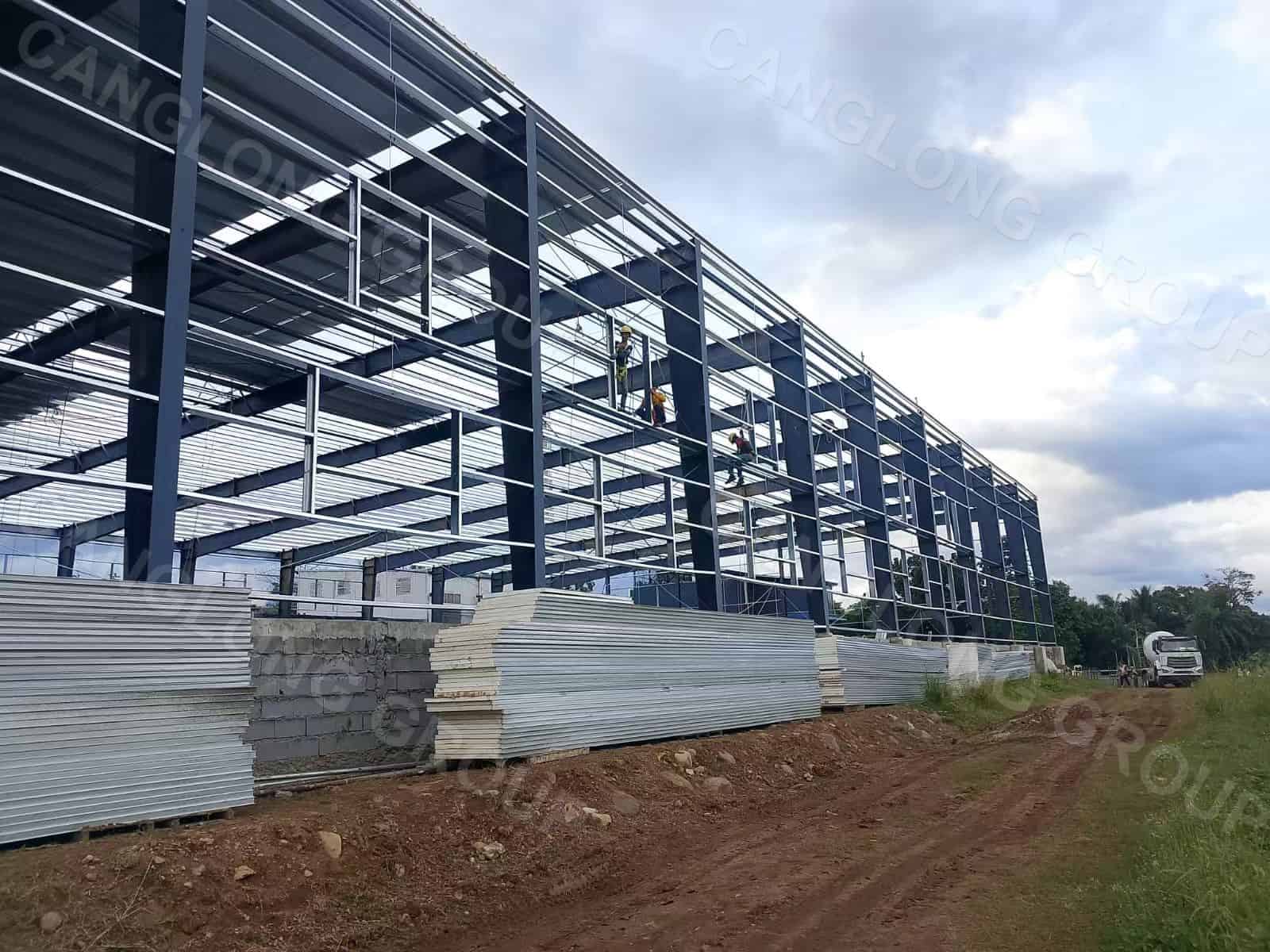
Double-slope, double-span frame in Q355 H-sections with galvanised C-purlins. The governing input was not wind or heat: it was two 20-tonne bridge cranes. Crane wheel loads set the column sections, the crane girders, and the longitudinal surge bracing, and once the crane data was fixed the rest of the design followed quickly. Walls are 4.2 m brick upstand with colour-coated sheet above; the roof is aluminium-zinc coated sheet with light-transmitting panels to cut daytime lighting load. Read the Thailand industrial plant case study.
Santiago, Chile — 40 m × 20 m × 8 m portal frame warehouse
An 800 m² storage building in a high-seismicity region. The frame is a conventional H-section portal, but the detailing is not: ductile connections, a clearly defined bracing system, and a deliberately light envelope using EPS sandwich panels. Keeping the roof mass down reduces the seismic force the frame has to resist, which is one of the quieter advantages of steel in earthquake zones. Read the Chile warehouse case study.
Selfoss, Iceland — 8 m × 11 m × 3.3 m storage godown
Only 88 m², and in some ways the hardest of the three. Small, light buildings are frequently governed by local wind suction at the corners and eaves rather than by snow, because there is so little dead load to resist it. The double-slope roof was chosen to shed rain and snow, the envelope uses PU sandwich panels for thermal performance, and all steelwork was blast-cleaned and coated in the factory for high-latitude exposure. Read the Iceland godown case study.
Across all three, the pattern is the same: the frame is a response to one or two dominant inputs, and the design quality is mostly a matter of identifying those inputs early. You can see the same logic applied across our project portfolio, from a 13,798 m² plant in Tashkent to prefabricated workshop buildings in the Pacific.
Design Standards Compared
A frame does not travel well between codes. The load combinations, the safety format and the serviceability limits all change, so a building designed to AISC 360 is not automatically compliant with Eurocode 3, even though the physics is identical.
| Region | Primary standard | Scope |
|---|---|---|
| UK & Ireland | BS EN 1993 (Eurocode 3) + UK/Irish National Annex | Steel design; superseded BS 5950. Actions from EN 1991 series; drift limits from the National Annex |
| European Union | EN 1993-1-1 to EN 1993-1-12 | General rules, cold-formed members, joints, fatigue, fire design |
| United States | AISC 360, with loads from ASCE 7 as referenced by the IBC | LRFD and ASD; seismic provisions from AISC 341; drift limits follow ASCE 7 |
| India | IS 800:2007 | Limit state design; loads from IS 875; seismic from IS 1893 |
| Singapore | BC1:2012 + SS EN 1993 | Singapore’s alternative structural steel provisions on top of Eurocode |
| Australia / New Zealand | AS 4100 / AS/NZS 4600 | Steel structures and cold-formed steel; actions from AS/NZS 1170 |
| Aspect | Eurocode 3 | AISC 360 | IS 800 |
|---|---|---|---|
| Design format | Limit state, partial factors on resistance | LRFD (or ASD) | Limit state |
| Common grades | S235, S275, S355 (Q235 / Q355 are the usual Chinese equivalents) | ASTM A36, A572 Gr.50 | Fe 410, Fe 490, Fe 540 |
| Factors | γM0 = 1.0, γM1 = 1.0, γM2 = 1.25 | φ ≈ 0.90 for yielding, 0.75 for tensile rupture | γm0 = 1.10, γm1 = 1.25 |
| Serviceability | Limits in the National Annex, not in EN 1993 itself | L/240–L/360 typical for beams; drift from ASCE 7 | Deflection limits in IS 800 Table 6 |
The practical consequence: switching an approved design from one code to another usually means re-running the load combinations from scratch, not resizing a few members. It is cheaper to decide the code at the enquiry stage than to convert later. Standard configurations drawn to a single code, such as our standard factory building, avoid that cost entirely.
For independent reading on steel design practice, the Eurocode repository from the European Commission’s Joint Research Centre, the AISC specifications and the industry-maintained steelconstruction.info case study library are all useful references.
Eight Mistakes That Cost Time and Steel
- Span fixed before the layout is fixed. The racking aisles, the production line or the crane coverage should determine the span, not the other way round.
- Wind uplift treated as a footnote. On a light steel roof it is frequently the governing case, and internal pressure assumptions change the answer.
- Crane data arriving late. Capacity alone is not enough. Without duty class, wheel loads and hook height, the columns, crane girders and bracing all have to be revisited.
- A heavy load discovered after the concrete is poured. Retrofitting crane girders or mezzanine supports to a frame analysed for neither means new columns and new footings, not an add-on bracket.
- A bracing bay deleted for a door. Easy on screen, expensive on site. Relocate bracing in the design.
- Foundations poured before final column reactions. The grid moves, the bolts do not.
- Fire rating and insulation chosen after the cladding. Panel thickness, core material and any applied protection are one decision, not three.
- Mixing codes. Members checked to one standard against load combinations from another is the most common error in converted designs.
Frequently Asked Questions
What does steel building structure design include?
Load determination from the site’s own wind, snow and seismic data; selection of the framing and bracing system; sizing of every primary and secondary member; connection design; foundation reactions; and the drawing package: general arrangement, shop drawings and erection drawings.
What information do I need before design can start?
Span × length × eave height, project location (coordinates, not just the city), intended use, crane or racking loads, door and opening schedule, insulation requirement, design code, and ideally a geotechnical report. The first five are usually enough to produce a budget proposal; the rest follows before the design is finalised.
Can you design to Eurocode, AISC, IS 800 or AS 4100?
Yes. Canglong Group’s design team works to EN 1993, AISC 360, IS 800, BC1 and AS 4100, and carries out independent code checks for export projects. Decide the code at enquiry stage — converting an approved design later is more expensive than designing to it from the start.
What are the main types of steel structural systems?
Six cover almost all industrial work: portal frame, multi-span portal, rigid (moment) frame, braced frame, truss or lattice, and space frame. Single-storey warehouses are usually portal frames; anything above roughly 36 m of width tends to move to multi-span or truss; tall or multi-storey buildings use rigid frames with braced bays. The system is chosen from what the building has to contain, then members are sized inside it.
What counts as a heavy-load steel structure?
Anything that leaves the standard envelope: overhead cranes above roughly 10 t, high-bay racking above about 10 m, loaded mezzanines, or process equipment supported by the frame. Each of those changes column sections, introduces fatigue-sensitive details, tightens deflection limits and usually enlarges the footings. Tell us at the enquiry stage — it is far cheaper than adding it later.
How is wind uplift handled on a light steel roof?
By combining external pressure coefficients with an internal pressure coefficient that reflects the real openings, then checking the roof-to-purlin fixings, the purlins, the rafter under net uplift, and the holding-down bolts in tension. Corner and eave zones get closer fixing spacing because local suction there is highest.
Who designs the foundations?
Normally a structural engineer registered in the country of construction, because soil data, frost depth and permit responsibility are local. The steel supplier provides the column reactions and the anchor bolt layout. Canglong Group supplies both as standard.
Do I need to decide on a crane now?
If there is any chance of one, yes — or at least reserve the column and girder capacity for it. Retrofitting crane brackets to a frame never designed for them is one of the more expensive changes available in a steel building.
How long does the design stage take?
For a typical 2,000–3,000 m² building, design and drawing approval runs 7–10 days once the inputs are complete. Fabrication is usually 20–25 days, shipping 15–35 days depending on destination. See the portal frame span, foundations and fabrication guide for a fuller breakdown.
Where to Go Next
If you are at the stage of choosing a building type, start with how to choose a steel warehouse type and which scenarios suit single-storey large-span warehouses. If the span is already fixed around racking, the interaction between clear span, forklift aisles and racking layout is covered in clear span, forklift and racking. For budgeting, see the pre-engineered metal building cost breakdown, and for supplier evaluation before you commit, the nine checks before you order a steel building from China.
Industrial applications are covered in more depth under industrial warehouses and industrial plant buildings, or browse the steel warehouse and steel factory building ranges.
Written and reviewed by the Canglong Group structural engineering team. Canglong has designed and fabricated steel buildings for export since 2005, working to EN 1993, AISC 360, IS 800, BC1 and AS 4100 across 80+ countries.
As a well-known steel structure construction supplier in China, Canglong Group has 20 years of industry experience and provides one-stop steel structure solutions from design to installation. We have a factory of 100000 square meters, and all our products have been certified by ISO and CE, and are sold to over 80 countries and regions worldwide.
Related Posts
 December 24, 2025
 July 14, 2026
 November 5, 2025
 April 9, 2026
Leave a Message
Your email address will not be published. Required fields are marked *
 October 16, 2026
 September 30, 2026
 September 7, 2026