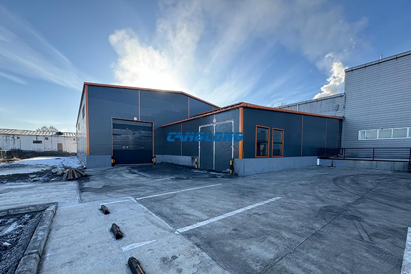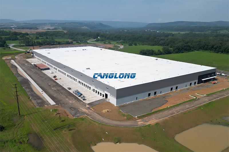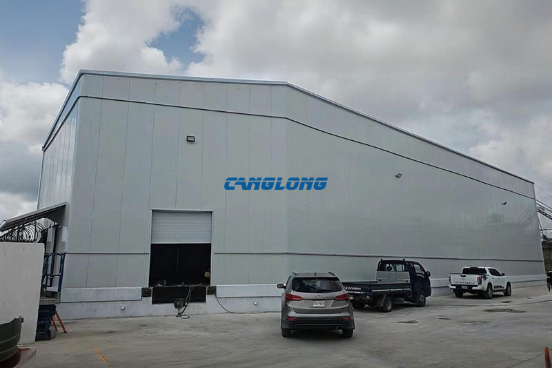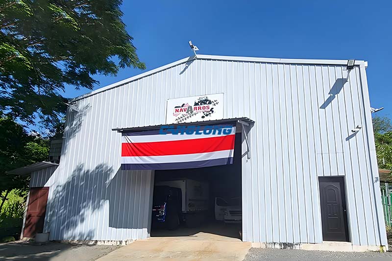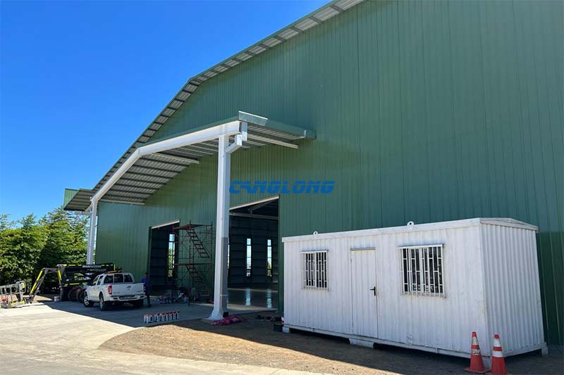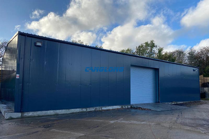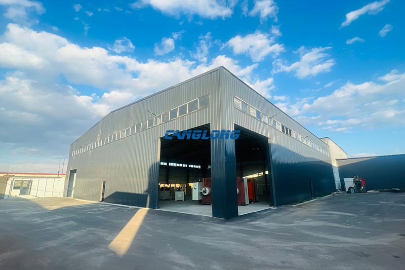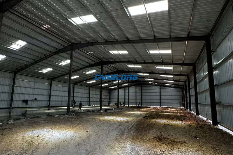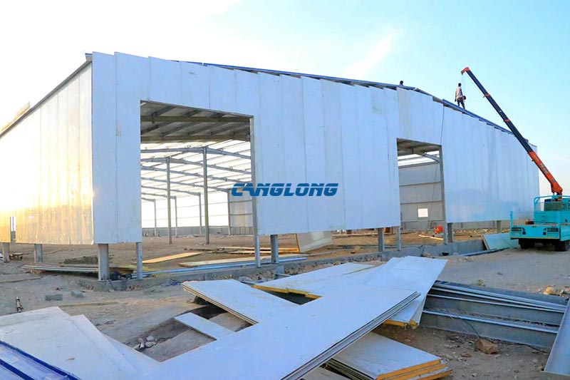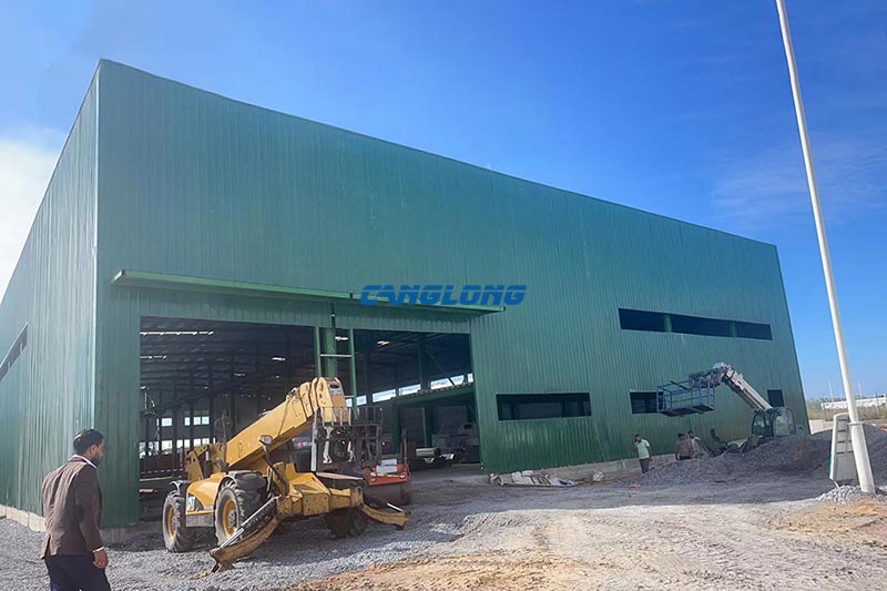
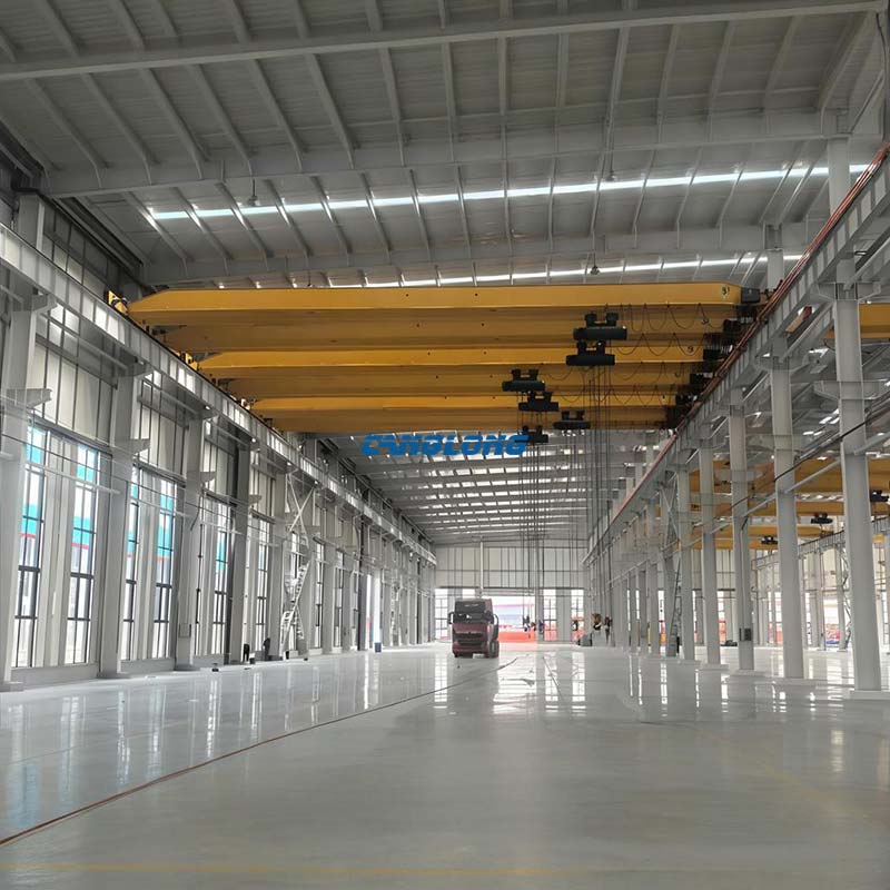
Factory Building With Crane
Structural Composition
Main Structural
Steel Structure
Steel Materials
Q235/Q355 Grade Steel
Beam/Column
H-Shaped Steel
Purlins
C/Z Section Steel
Wall/Roof System
Insulation Panel (EPS/PU/Rock Wool), Metal Sheet
Accessory
Crane, Drainage Pipe, Door, Window
Service Life
Over 25 Years
Delivery Time
30 Days After Receiving the Deposit
Payment
T/T, L/C, PayPal
A factory building with crane is not a standard factory shed with an overhead crane bolted on afterwards. The crane decides the structure. Its capacity and wheel loads set the column section, the bracket and the runway beam. Its hook height sets the eave height. Change the crane after the steel has been rolled and there is no cheap way back.
Canglong Group designs and fabricates crane-served steel factory buildings for manufacturing, assembly, maintenance and heavy materials handling. Our scope runs from the structural calculation and the crane bracket / runway beam detail through fabrication, shipment and site assembly guidance, so the hoist, the rail and the steel frame are engineered as one system instead of three separate purchases.
That single sequence is what separates a crane building that works from a steel building with an overhead crane fitted to it afterwards.

What Makes a Crane Building Different From a Standard Factory
On a factory without lifting equipment, roof and wind loads usually govern the frame. Once a travelling crane is introduced, the governing load changes. A loaded crane produces vertical wheel loads, lateral surge forces from acceleration and braking, and longitudinal forces from crab travel. Those forces repeat thousands of times a year, so the design is driven by fatigue as much as by strength.
| Design point | Standard factory building | Factory building with crane |
| Governing load | Roof live load, wind, snow | Crane wheel loads plus lateral and longitudinal crane forces |
| Column design | Axial compression and bending from wind | The same, plus a concentrated bracket load applied off-centre |
| Deflection control | Roof deflection under snow | Rail deflection under the trolley, plus a column sway limit (commonly H/400 or tighter) |
| Detailing | Standard bolted connections | Crane bracket, runway beam, rail clips, end stops, rail-level walkway where serviced at height |
| Critical detail | Rarely fatigue-governed | Fatigue at the bracket-to-column weld and at the runway beam web |
The Crane Runway System: Brackets, Runway Beams and Rails
Most of the engineering that makes a crane building work is concentrated in a small zone at the top of each column. It is also where suppliers who only sell “a steel building” tend to leave gaps for someone else to close.
Crane column brackets
Brackets are welded to the column at rail level and carry the runway beam and the rail. On lighter buildings they are shop-welded plate brackets. Where the crane is heavier, or the bracket carries a large off-centre load, they are built as a stiffened bracket with a full-penetration weld through the column flange. This joint is the most fatigue-critical detail in the whole building, so it is welded and inspected in the factory rather than on site.
A terminology note for anyone reading imported drawings: these brackets are called crane brackets, column brackets or corbels. Older translations of Chinese drawings sometimes render the term literally, which makes a quotation hard to check against a structural drawing. Corbel is the word your engineer will expect to see.

Crane runway beams
The runway beam is not a roof purlin scaled up. It is designed for the crane wheel load with a dynamic amplification factor added, plus the lateral force from trolley travel, and it is checked for fatigue, web buckling and lateral-torsional restraint. Depending on span and capacity we fabricate runways as rolled H-sections or as welded plate girders with a stiffener under every rail seat, so the wheel load arrives at a stiffener instead of mid-web.
Rail, clips and end stops
Rail is fixed with clips that let it expand and contract without losing gauge. End stops are fitted at both ends of the runway so a crane cannot travel past the last column. Where a crane has to be serviced at height, a walkway and rail-level platform can be detailed into the same bracket instead of being added later.
Bracing and lateral stability
A moving crane loads the frame sideways, not only downwards. Roof and wall bracing is coordinated with the runway level so those lateral forces have a continuous path down to the foundation, and column sway limits are set to suit the crane class rather than the wind case alone.
Sizing the Building Around the Overhead Crane
Eave height and hook height
The most common mistake on a crane building is fixing the eave height before the lifting requirement is known. The reliable sequence works backwards from the hook, and it holds whether the crane is a single-girder unit or a heavy EOT (electric overhead travelling) double-girder crane:
Eave height = hook height required + clearance under the load + crane depth + rail and runway beam depth + clearance to the underside of the rafter
The table below shows the range our crane-served factory buildings usually land in, for a single-bay industrial building with a top-running crane. The real figure depends on the crane maker’s own dimensions, which we ask for before the runway beam is detailed.
| Crane | Typical rail top level | Eave height usually required |
| 5 t, single girder | 6 – 7 m | 8 – 9 m |
| 10 t, single girder | 7 – 8 m | 9 – 10 m |
| 10 t, double girder | 8 – 9 m | 10 – 11 m |
| 20 t, double girder | 9 – 10 m | 11 – 12 m |
| 32 t, double girder | 10 – 12 m | 12 – 14 m |
| 50 t, double girder | 12 – 14 m | 14 – 16 m |
Two things worth knowing about that table. A clearance is always kept between the highest point of the crane and the underside of the rafter so the frame is never struck during travel. And every extra metre of eave height adds steel, cladding and heated volume across the entire floor area, so on a 1,000 m² building the height should be set by the lifting task rather than rounded up for comfort.

Loads the frame is designed for
| Load | Source | Range we normally design to |
| Crane vertical wheel load | Crane maker’s data, per wheel | 50 – 1,500 kN |
| Crane lateral and longitudinal force | Acceleration, braking, crab impact | Class dependent, typically 5 – 10% of wheel load |
| Roof live load | Maintenance access, suspended services | 0.3 – 0.7 kN/m² |
| Wind, snow, seismic | Project location and applicable code | Per local code |
What We Need From You Before We Design the Runway
A preliminary frame scheme can be issued from a building size and a crane capacity. A final structural calculation needs the crane data. If any value below is still open, say so, and we will design a generous provisional case rather than leave the question unresolved.
| Information | Why it changes the steel |
| Crane capacity (t) | Sets the wheel load, and therefore the runway beam and the bracket |
| Crane span (m), rail centre to rail centre | Sets the runway beam span and usually the building width |
| Number of cranes and whether they share a runway | Two cranes on one runway load a single column through two brackets at different levels |
| Duty class (A3 – A7, ISO M3 – M7, CMAA Class C – F) | Sets the fatigue check, so a higher class needs heavier detailing for the same capacity |
| Maximum wheel load per wheel (kN) | This figure, not the capacity in tons, drives the runway beam design |
| Rail top level and hook height required (m) | Sets the bracket elevation and the eave height |
| Crane maker and model, if already ordered | The bracket and rail fixing are detailed to that maker’s own dimensions |
| Building length, width, eave height, bay spacing | Basic geometry for the frame model |
| Project location and wind / snow / seismic conditions | Load cases for the calculation |
| Foundation type and soil bearing capacity | The bracket produces a large overturning moment at the base plate |
Single Girder or Double Girder?
Both work. They do not produce the same building, and the decision needs to be made before the runway beam is fabricated because the bracket geometry differs.
| Single girder | Double girder | |
| Capacity range | Typically up to about 20 t | 5 t to 50 t and above |
| Hook height for a given eave height | Lower, because the hoist hangs below the girder | Higher, because the trolley sits between the girders |
| Load on the building | Lighter runway and bracket | Two rails, a wider bracket, heavier columns |
| Best fit | Maintenance bays, moderate duty cycles, lower lifts | High hook heights, heavy or long loads, frequent cycles |
The crane type belongs to your lifting supplier and your process, but it has to be fixed before we detail the runway. Buyers sometimes bring a crane quotation to us for a second opinion on the wheel loads quoted against it, which is a sensible check to run before either order is placed.

Crane Duty Class, and Why It Changes the Steel
“20 tons” describes the load. It does not describe how hard the crane works. Duty class does.
A crane in a maintenance bay that lifts a few times a day and a crane on a production line cycling every few minutes can both be rated 20 t, but they do not load the building the same way. The first sits in light duty territory (around A3 – A4, ISO M3 – M4, CMAA Class C). The second is closer to A6 – A7, ISO M6 – M7. For the second we increase the fatigue detailing: full-penetration welds at the bracket, a stiffener under every rail seat, tighter limits on runway beam deflection and on column sway, and heavier rail fixings.
This is also why two crane-building quotations can differ by a wide margin and both be “honest”. A buyer comparing on price alone is often comparing a light-duty detail with a heavy-duty one without knowing it. It is worth asking the question directly before you order.
Steel Grade, Coating and Enclosure
Main frames are fabricated from Q235B or Q355B welded H-sections. Q355B carries the same load in a lighter section, which is why it is our default where the bracket load is high; Q235B remains competitive where the crane is light and the span is short. Where a project has to satisfy another code, we fabricate to ASTM A992 or EN 10025 equivalents.
Surface protection is decided by the site rather than by preference.
- Shot blasting to Sa 2½ with an epoxy primer and a polyurethane or PVDF topcoat for inland and general industrial environments.
- Hot-dip galvanizing for coastal, humid and chemical environments. The Panama crane building below is fully galvanized, because salt-laden air at that site would attack a painted frame at the bolted connections within a few years.
Roof and wall systems are chosen separately from the frame: insulated sandwich panels where the process needs temperature control or a clean internal finish, single-skin profiled sheet with a liner where it does not. Crane halls also need high-level ventilation, because heat and fumes collect in the upper part of the building, which is exactly where the crane and the operator work.
What Drives the Cost of a Factory Building With Crane
Four things move the price more than anything else:
- Crane capacity and wheel load, which drive the runway beam and the bracket
- Eave height, which multiplies across the whole floor area
- Duty class, which decides how much fatigue detailing is required
- Crane span, which decides whether the building needs an intermediate column row
Three of those four are decided by your production process, not by the supplier. For how the frame itself is calculated, see our guide to design standards for steel structure factories. For how steel building pricing is put together, see the pre-engineered metal building cost guide.
Crane Buildings Canglong Has Delivered
Three recent projects show how differently the same product is configured, depending on the crane and the climate.
- Panama City, Panama (2024) — 2,380 m², 70 m × 34 m × 12 m. Double-slope, double-span frame with a single intermediate column row, giving an open internal space for large shelving and heavy vehicle movement. Columns, beams and crane beams are fully galvanized H-sections, selected for Panama’s humid, salt-laden maritime air. Runway beams are carried on the structural columns. See the Panama crane building project.
- Phitsanulok, Thailand (2023) — 400 m², 20 m × 20 m × 9 m. H-section beam and column frame with runway beams designed and reinforced for repeated dynamic lifting loads. Insulated profiled roof panels to hold back tropical heat, with decorative sandwich panel walls for sealing and corrosion resistance. See the Thailand crane building project.
- Douala, Cameroon (2023) — a double-slope, double-span factory served by a single-girder crane, with a Q235B H-section frame and a 2 m brick wall at the base for impact resistance and thermal performance in a hot, humid climate. See the Cameroon factory with crane project.
- Bangkok, Thailand (2025) — 7,228 m², 184 m × 42 m, brick base wall to 4.2 m. A double-slope, double-span Q355B H-section frame carrying two 20-ton overhead bridge cranes on a full-length runway, the heaviest crane duty on this page. Purlins and the support system are hot-dip galvanized C-section; the roof is 840-type and the walls 900-type aluminium-zinc coated colour-coated corrugated sheet with a stated 50-year panel service life, with solar skylights for daylighting and steel louvre plus aluminium sliding windows for ventilation. Drawings were designed and confirmed to Thai standards. See the Bangkok industrial plant project, 7,228 m².

Where These Buildings Are Used
These are pointers rather than a full list. The structural answer depends on the crane and the process, not on the name of the industry.
- Heavy machinery and equipment manufacturing — an industrial factory building with a runway sized to the heaviest single lift
- Steel and metal processing — see steel factory building solutions for process-driven layouts
- Assembly and maintenance bays — often a prefabricated workshop building with a lighter single-girder runway
- Long and heavy materials storage — a large span warehouse frame carrying a runway over the storage bays
Frequently Asked Questions
Can a crane be added to an existing factory building?
Usually, but rarely cheaply. Existing columns generally need reinforcing by welding additional plates to the flanges, the bracket needs a load path into a column that was never designed to receive it, and the concentrated wheel loads often require new pad footings under the crane columns. In practice a retrofit frequently costs more than the difference between a crane-ready building and a plain one at the time of the original order. If a crane is possible within five years, engineer for it now.
What eave height do I need for a 10 ton overhead crane?
For a top-running 10 t crane, the rail top level usually lands around 7 – 9 m and the eave height works out at roughly 9 – 11 m, depending on whether the crane is single or double girder and how much clearance you need under the hook. The reliable way to set it is to fix the hook height your tallest lift requires, then add the crane’s own depth and the clearance to the underside of the rafter.
Do you supply the crane as well as the building?
Whether the crane itself is purchased through us depends on the project and on whether you already have a lifting supplier in your country. What we always supply is the structure engineered around your crane: the bracket, the runway beam, the rail fixings and the frame. We work to the crane maker’s own dimensional data, and we recommend confirming that data before fabrication starts rather than after.
What crane capacity can you design for?
Our standard range covers 5 t to 50 t travelling cranes, single or double girder, with runway beams fabricated as welded plate girders where the wheel load demands it. Beyond that, capacity is limited by the span and by what can be shipped in standard containers, so it is reviewed as a project rather than quoted from a list.
Can the building be extended later?
Yes, if it was planned. Extending a crane building is straightforward where the original frame was detailed with a future bay in mind and the crane runway can continue at the same level. It is much harder if the gable frame was designed as a closed end. Mention a possible extension at the enquiry stage and it costs very little to allow for.
Which coating should I choose for a humid or coastal site?
Hot-dip galvanizing for the main frame and for the crane brackets. Paint systems depend on site maintenance being carried out on schedule, and touch-up around brackets and bolt groups is the part that gets missed. Galvanizing costs more up front and removes that risk entirely.
Get a Quotation for Your Factory Building With Crane
Send us the crane capacity, span, hook height and duty class if you have them, together with the building length, width, eave height and project location. If the crane has not been chosen yet, tell us what the building has to lift and how often, and we will size a provisional runway case so the frame design is not held up.
You will receive a preliminary structural scheme, a crane bracket and runway beam detail, and a quotation covering fabrication and delivery.
Request a crane building quotation →
Color Selection of Steel Structures
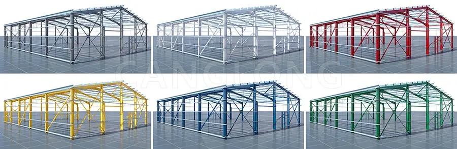
Steel Building 3D Model Design
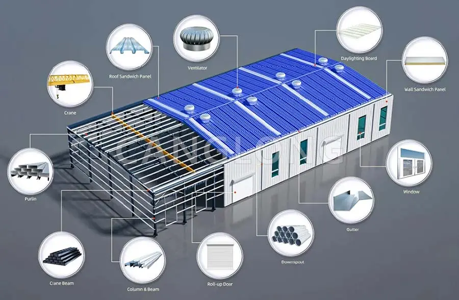
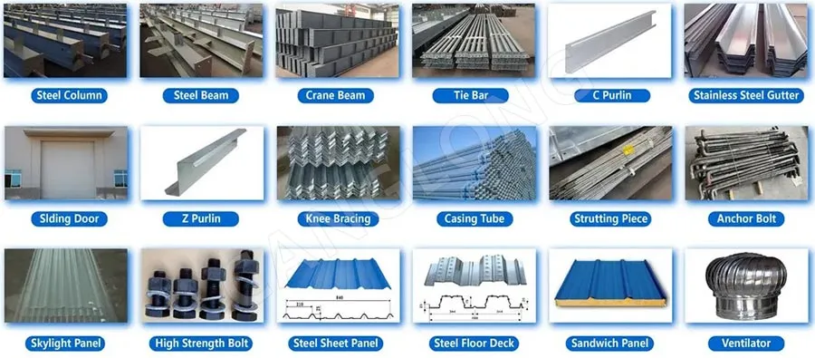
Steel Structure Building Kits
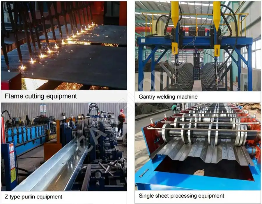
Steel Structure Production Equipment
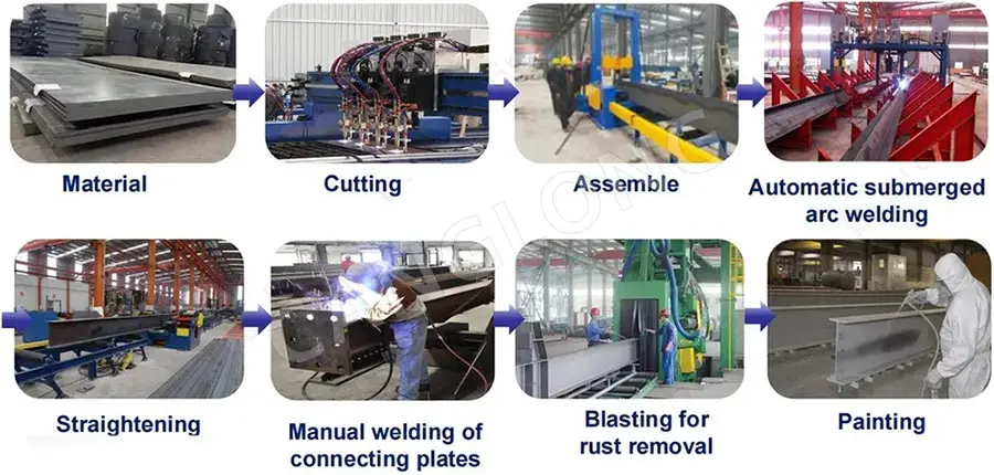
Steel Structure Production Process
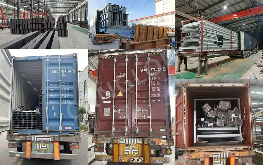
Packing And Shipping
Why Choose Us?
- The first and largest steel structure & sandwich panels factory in north of China.
- 20 years experience direct factory with competitive price, stable and controllable quality.
- Over 100 million dollars of annual output.
- More than 100000m2 production industrial park.
- One stop service from design to installation.
- 10 units free 3D designs & 10 units design structural drawings per day.
- Professional installation teams in 30+ countries.
- CE,ISO certificates.
- Supply quality guarantee for 15 years.
- Cooperating with 100+ countries & 2000+ partners.
Get A Free Quote
Your email address will not be published. Required fields are marked *
Global Project Release
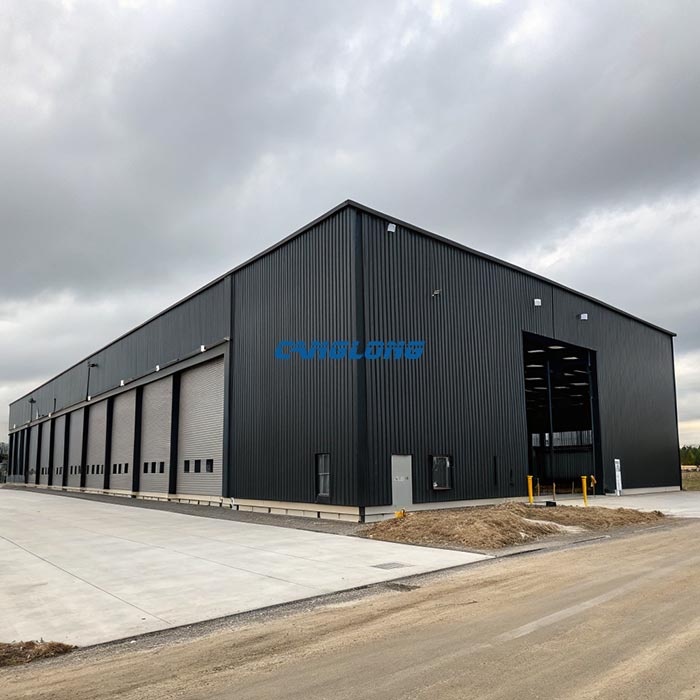
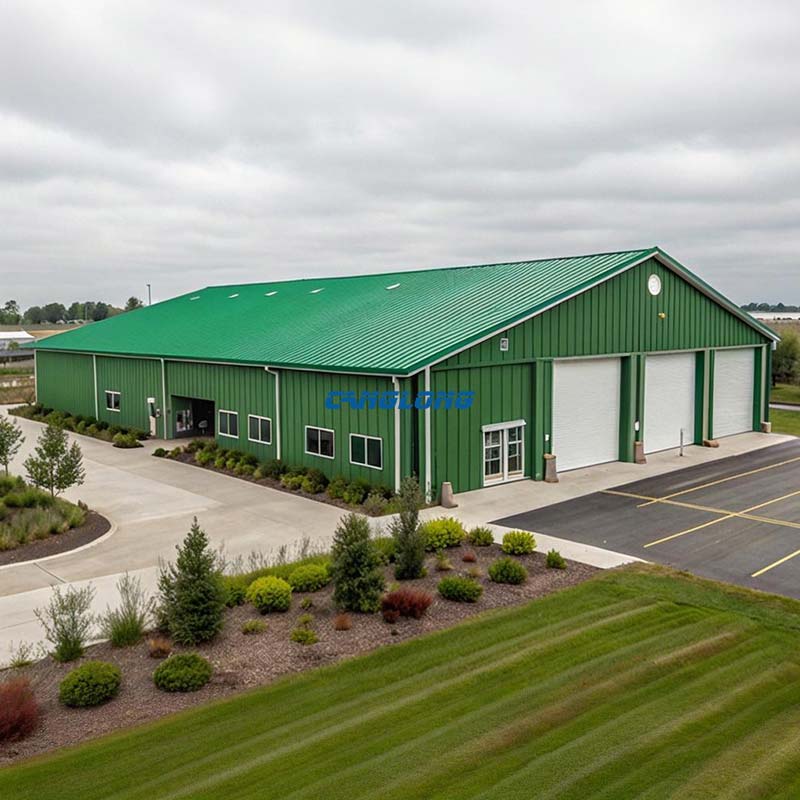
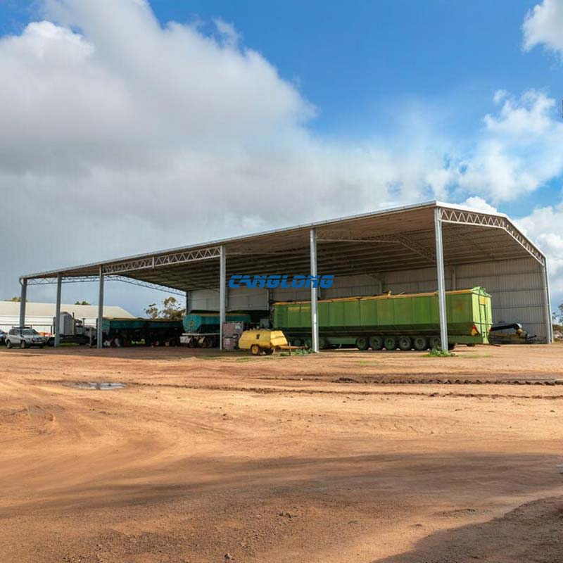
Canglong projects cover more than 120 countries and regions around the world, providing one-stop steel structure building solutions from design to installation.